1 # IBM 5291 keyboard converter
3 [IBM 5291](https://deskthority.net/wiki/IBM_Model_F#IBM_5291_Keyboard)
5 A converter for the eponymous keyboard.
7 Keyboard Maintainer: [Listofoptions](https://github.com/listofoptions)
8 Hardware Supported: IBM 5291, Teensy 2.0
10 Make example for this keyboard (after setting up your build environment):
12 make converter/ibm_5291:default
14 See the [build environment setup](https://docs.qmk.fm/#/getting_started_build_tools) and the [make instructions](https://docs.qmk.fm/#/getting_started_make_guide) for more information. Brand new to QMK? Start with our [Complete Newbs Guide](https://docs.qmk.fm/#/newbs).
17 The pinout is as follows:
19 IBM−5291−Cable to Pinhead−14
22 ----|------------------------
38 The pins on this connector are organized
39 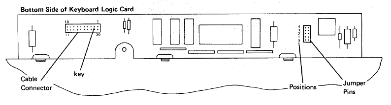
41 IBM−5291−2 Cable with DB15M connector
59 The above connector is actually numbered so it should be easier to determine
60 where the needed connections are.
62 To connect to the teensy, the following are pins are needed (if you should choose not set your own):
64 * PB0 -> PB6 are connected to D0 -> D6
65 * +5V is connected to the corresponding teensy pin
66 * gnd is as well, only one of the gnd pins needs to be connected though.
67 * strobe is connected to pin PD1
68 * data is connected to PD0
69 * PE does not need to be connected to anything, but it could also be connected to gnd
72 http://www.retrocomputing.eu/documents/5291_MaintenanceLibrary.pdf